|
|
|
Categories
|
|
Information
|
|
Featured Product
|
|
|
 |
|
|
There are currently no product reviews.
 ;
Came in the mail within a few hours. Gave clear instruktion on maintaines. Is of great use to have this manual in house
 ;
Easy to access. Clear instructions. No problems. Printed fine.
;
Great scan but please note that it is entirely in GERMAN.
;
High quality scan of the manual, very quick and easy download and very important, a truly honest price. thanks
;
Minden rendben, de két megjegyzés, az ábrák nehezen kivehetők és a fizetés után 24 órát kell várni a letöltésre.
TM 11-6625-1538-15
Section V Paragraphs 5-21 to 5-31 and Table 5-4 and Figure 5-2 Table 5-4. 1/3 Scale Tracking Tolerances (400 EL) 10 VOLT RANGE FREQUENCY Hz 10 40 100 1000 , 10 K 500 K lM 4M 10 M METER READING MIN 2.70 2.96 2.96 2.96 2.96 2.94 2.94 2.88 2.70 MAX 3.12 3.04 3.04 3.04 3.04 3.06 3.06 3.06 3.07 DC OUTPUT MIN 0.270 0.297 0.297 0.297 0.297 0.294 0.294 0.288 0.270 MAX 0.312 0.303 0.303 0.303 0.303 0.306 0.306 0.306 0.309 10 40 100 1000 10 K 500 K lM 4M 10 M FREQUENCY Hz 3 VOLT RANGE METER READING MIN 0.90 0.98 0.98 0.98 0.98 0.98 0.98 0.96 0.90 MAX 1.04 1.02 1.02 1.02 1.02 1.02 1.02 1.02 1.03 DC OUTPUT MIN 0.284 0.311 0.311 0.311 0.311 0.311 0.310 0.304 0.284 MAX 0.304 0.321 0.321 0.321 0.321 0.321 0.322 0.322 0.325 Model 400E/EL
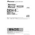
5-21. INPUT CAPACITY CHECK.
Figure 5-2. Input Impedance Check specifications. If the instrument cannot be properly adjusted, refer to the Troubleshooting Procedures a. Connect a test oscillator, a 100 K � resistor, (Paragraph 5-34). Figure 5-3 shows the location of and the 400E/EL as shown in Figure 5-2. Inall the internal adjustments. sert the resistor lead directly into the BNC connector on the 400E/EL, and connect the 5-24. COVER REMOVAL. ground lead to the outer shield of the 400E/EL input connector. Do not use an adapter, as 5-25. To remove the top or bottom covers, remove any adapter will add input capacity. the Phillips screw at the rear of the cover, slide the cover about 1 inch to the rear, and lift if off. To reb. With the 400E/EL on the 3 volt range, adjust place the cover, reverse the removal procedure. the test oscillator for a full scale reading on the 400E/EL at 40 Hz. 5-26. To remove a side cover, remove the four Phillips screws and lift it off. c. Increase the test oscillator frequency until the 400E/EL indication drops to 2.12 volts. 5-27. BIAS ADJUST. This should occur at a frequency of 180 KHz or greater, verifying an input capacity of 8 5-28. Connect a dc voltmeter (410C) to TP3 and adjust pf or less on the 3 volt range. A2R17 for -6.0 ±0.25 vdc. Connect a dc voltmeter to TP4 and adjust A2R31 for +10.0 ±0.5 vdc. d. Repeat steps a and b with the 400E/EL on the 1 volt range. 5-29. AC OUTPUT ZERO. e. Increase the test oscillator frequency until the 400E/EL indication drops to 0.707 volts. This should occur at a frequency of 72 KHz or greater, verifying an input capacity of 21 pf or less on the 1 volt range. 5-30. Connect a dc voltmeter (410C) to TP5 and adjust A2R59 for 0.0 ±0.050 vdc. 5-31. CALIBRATION. NOTE If a 400E/EL Otpion 02 is to be calibrated, set the REL. REF adjustment to the fully clockwise ABSOLUTE position before beginning the calibration. 01788-1
5 - 2 2 . ALIGNMENT AND CALIBRATION PROCEDURE. 5-23. The calibration adjustments are �cover off� procedures to adjust the 400E/EL to its performance 5-4
|
|
|
> |
|